A Series Circuit Has Which of the Following
Introducing the resistor increases the decay of these oscillations which is also known as damping. An RC series circuit.

Series Circuits Basic Electricity
Impedance Calculation in RC Series Circuit Example 1.

. In this section we see how to solve the differential equation arising from a circuit consisting of a resistor and a capacitor. The circuit forms a harmonic oscillator for current and resonates in a similar way as an LC circuit. The basic components used in the circuit inductance L represents crystal mass capacitance C2 represents compliance and C1 is used to represent the capacitance that is formed because of crystals mechanical moulding resistance R represents the crystals internal structure friction The quartz crystal oscillator circuit diagram consists of two resonances such as series and parallel.
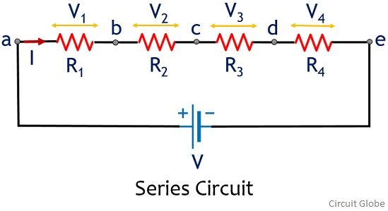
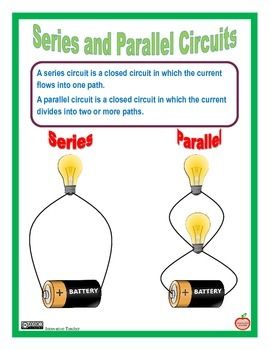
A series circuit has only one path through which its current can flow. The general strategy to accomplish this goal is as follows. Determine the total voltage electric potential for each of the following circuits below.
So for complete analysis of series RL circuit follow these simple steps. Circuit A Circuit B 3 A CIRCUITS WORKSHEET 1. An LCR circuit is an electrical circuit consisting of a resistor R an inductor L and a capacitor C connected in series or in parallel.
In a series circuit there is just one path so the charge flow is constant everywhere charge is not lost or. 13V 12 V 3. When the resistance and capacitive reactance of a series RC circuit are known the impedance is found using the equation.
This circuit has three sections. Z RC is the RC circuit impedance in ohms Ω. Therefore all of the components in a series connection carry the same current.
When voltage is. In series RL circuit the values of frequency f voltage V resistance R and inductance L are known and there is no instrument for directly measuring the value of inductive reactance and impedance. F is the frequency in hertz Hz.
Since the value of frequency and inductor are known so firstly calculate the value of inductive. As has been the case since 2017 equal prize money will be on offer in both the mens and womens series and further details on the 2022 national championships for road time-trial and circuit will be published in due course. The first section is between the battery and the 10 Ω resistor red color the second section has two unknown identical resistors in.
ω 2πf is the angular frequency in rads. The following formulas are used for the calculation. See the related section Series RL Circuit in the previous section In an RC circuit the capacitor stores energy between a pair of plates.
Guidelines to Series-Parallel Combination Circuit Analysis. Heading into this weekend at the Circuit of The Americas the NASCAR Cup Series has 11 former road course winners entered in the EchoPark Automotive Grand Prix this Sunday March 27 at 330 pm. Assess which resistors in a circuit are connected together in simple series or simple parallel.
φ is the phase difference between the total voltage V T and the total current I T in degrees and radians and. Determine the equivalent total resistance for each of the following circuits below. The goal of series-parallel resistor circuit analysis is to be able to determine all voltage drops currents and power dissipations in a circuit.
Series circuits are sometimes referred to as current-coupled or daisy chain-coupledThe electric current in a series circuit goes through every component in the circuit. An AC series RC circuit is made up of a resistor that has a resistance value of 20 Ω and a capacitor that has a capacitive reactance value of 30 Ω. R is the resistance in ohms Ω.
C is the capacitance in farads F.

Pin On Science
Difference Between Series And Parallel Circuit With Comparison Chart Circuit Globe
Physics Tutorial Series Circuits

Series Circuit Science Education Science Journal 5th Grade Science

Pin On Science

Pin On News To Go
Series And Parallel Circuit Series And Parallel Circuits Science Electricity Science Fair Board

Circuits Quiz Science Teaching Resources Quiz Simple Circuit
Electricity Current In Series Parallel Pathwayz

Electricity Lapbook Lapbook Electricity Activities Series And Parallel Circuits

Series Circuit Working Principle Characteristics Applications Advantage

Building Electric Circuits Stem Challenge Cards Paper Circuits Electric Circuit Stem Challenges
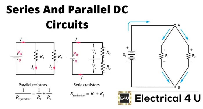
Series And Parallel Dc Circuits Explained Examples Included Electrical4u
Electrical Electronic Series Circuits

What Is The Difference Between Series And Parallel Circuits My Electrical Diary

Building Electric Circuits Stem Challenge Cards Etsy Stem Challenges Electric Circuit Kids Stem Activities

Series And Parallel Circuit Series And Parallel Circuits Homeschool Science Creative Teaching

Building Electric Circuits Stem Challenge Cards Etsy Electric Circuit Paper Circuits Stem Challenges
Parallel And Series Circuit Clip Art Circuit Simple Circuit Clip Art


Comments
Post a Comment